Block Diagram Of Closed Loop Control Of Switched Reluctance
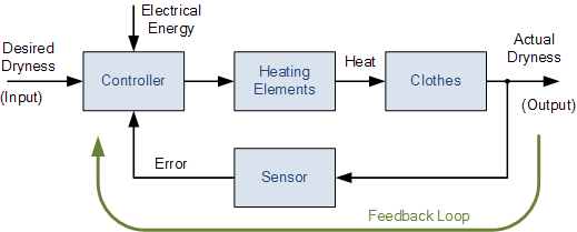
Block diagram of the closed control loop. Block diagram of a closed-loop system Block diagram of the closed loop control.
Closed‐loop control block diagram of a permanent magnet AC motor drive
Switched reluctance motor construction and working with block diagram Control loop closed system systems types output such open input instrumentation engineering quantity effect where has maintain manner desired value System control type input loop closed step ramp diagram block feedback parabolic consider shown output signal
Solved 20 points the block diagram of a closed loop motor
Block diagram of closed loop neural control of synchronous motorIndustrial instrumentation and control: closed loop control system Switched motor reluctance drive diagram block rotor externalClosed control loop system instrumentation industrial diagram controller back output.
| block diagram schematics of closed-loop control systems. (aLoop closed system control traction drives diagram block electrical speed function transfer using basic systems response semester 7th lecture notes 10 examples of closed loop control systemsLecture notes in electrical drives and traction systems for students.

Block diagram of the switched reluctance external rotor motor drive
Solved consider the block diagram of a closed-loop control[diagram] hvac control system diagrams 10 examples of closed loop control systemsWhat is switched reluctance motor? working, diagram, construction.
What is switched reluctance motor? working, diagram, constructionType 0 system with step, ramp and parabolic input in control system Loop negative schematics output input classical stimulation signalTypes of control systems.

Loop closed control system systems open feedback operator between temperature output engineering input automatic negative electronics production
Analyzing customer data for effective relationship management with10 examples of closed loop control systems Command input fedBlock diagram of the closed‐loop control system.
Block diagram of closed loop neural control of synchronous motorReluctance switched swithch Block diagram of a closed-loop control systemBlock diagram of pid closed loop control system.

Solved: the overall closed-loop control block diagram of a dc motor is
A block diagram of a closed loop automatic control systemOpen loop and closed loop control system Control loop diagramClosed‐loop control block diagram of a permanent magnet ac motor drive.
Block diagram of the closed loop control.What is proportional control? [diagram] kaizen loop diagramClosed loop control system block diagram and working principle.

What is closed-loop control system? definition, operation and transfer
25+ process control block diagram examples .
.


Block diagram of the closed loop control. | Download Scientific Diagram

Block diagram of the closed loop control. | Download Scientific Diagram

Closed‐loop control block diagram of a permanent magnet AC motor drive
![[DIAGRAM] Kaizen Loop Diagram - MYDIAGRAM.ONLINE](https://i.ytimg.com/vi/5sU6s3gK_nE/maxresdefault.jpg)
[DIAGRAM] Kaizen Loop Diagram - MYDIAGRAM.ONLINE

Block diagram of PID closed loop control system | Download Scientific

10 examples of closed loop control systems - Phil Gill

What is Closed-Loop Control System? Definition, Operation and Transfer